General Information
EMI(Electro-Magnetic Interference) Filters, basically are passive electronic devices that are used to suppress conducted interference that is found or a signal or power line. Electro-Magnetic Interference(EMI) is unacceptable electro-magnetic radiation, natural or man-made, which result in the degradation or malfunction of electronic or electrical equipment. Radio Frequency Interference(RFI) is detrimental electrical energy in the frequency range, which is for the specific transmitted radio frequency.
The properties of EMI/RFI filter as follows:
- Wide capacitance range
- Low self-inductance
- High attenuation for frequencies
- Up to 3GHz
- Extensive style program
- Smallest dimensions
- Resistibility to voltage impulses
The main application are:
Entertainment electronics,Office and data processing,Telecommunications,Aeronautics technics,Automotive electronics,Industrial electronics
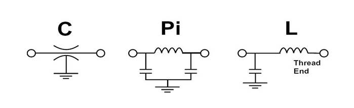
Circuit available in this catalog:
Ceramic Type II and III Temperature Characteristic Table
| The first letter (indicate lowest temp.) | The second number (indicate highest temp.) | The third letter (indicate capacitance change rate) |
| X -55℃ Y -30℃ Z ±10℃ | 4 +65℃ 5 +85℃ 6 +105℃ 7 +125℃ 8 +150℃ | A ±1.0% |
| B ±1.5% | ||
| C ±2.2% | ||
| D ±3.3% | ||
| E ±4.7% | ||
| F ±7.5% | ||
| P ±10% | ||
| R ±15% | ||
| S ±22% | ||
| T +22% -33% | ||
| U +22% -56% | ||
| V +22% -82% |
Common Temperature Characteristic Code Chart
| EIA Code | NPO | N150 | N220 | N470 | N750 | SL | Y5P | Y5U | Y5V |
| GB Code | CH | PH | RH | TH | UJ | SL | 2B4 | 2E4 | 2F4 |
Technical Parameter Term:
1. Capacitance(Cap):
Capacitance, expressed in “FARADS”, is the capability of two of more parallel conductive plates to store electrical energy in an electrostatic filed between them. Capacitance is dependent on the properties of the dielectric material and the geometry of the capacitor. (See table below)
2. Dissipate Factor (D.F.):
Dissipate Factor is defined as the ratio of energy dissipated to energy stored in a dielectric. It is frequency sensitive and must be specified at a specific frequency.
3. Dielectric Withstand Voltage(D.W.V.):
The peak voltage that a component is designed to withstand, without damage for short periods of time.
4. Insertion Loss(I.L.) or Attenuation:
The loss in load power due to the insertion of a component or device at some point in a transmission system.
5. Insulation Resistance (I.R.):
I.R. is the DC resistance between the terminal and ground of the a capacitor. It is generally measured at the rated voltage of the capacitor, and must be specified in terms of voltage, temperature, time and relative humidity.
●Conversion (For example:10,000pF=10nF=0.01uF)
| pF(pico Farads) | nF(nano Farads) | uF(micro Farads) |
| 1 | 0.001 | 0.000001 |
| 1,000 | 1 | 0.001 |
| 10,000 | 10 | 0.01 |
| 100,000 | 100 | 0.1 |
| 1,000,000 | 1,000 | 1.0 |
Installation Notice
The core of EMI filter is discoidal capacitor and tubular capacitor.The same as other ceramic products,it will damage because of temperature abrupt change,mechanical shock and extreme voltage.So we need to pay attention when we install EMI filter on the board,lead and shape need to reduce every stress to the lowest carefully.
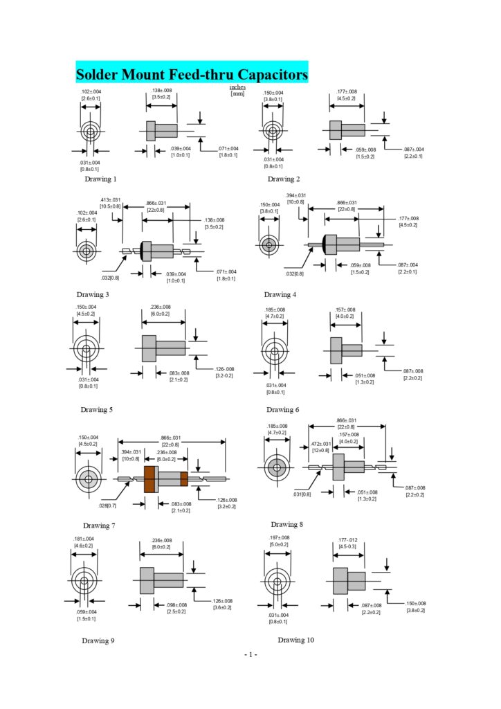
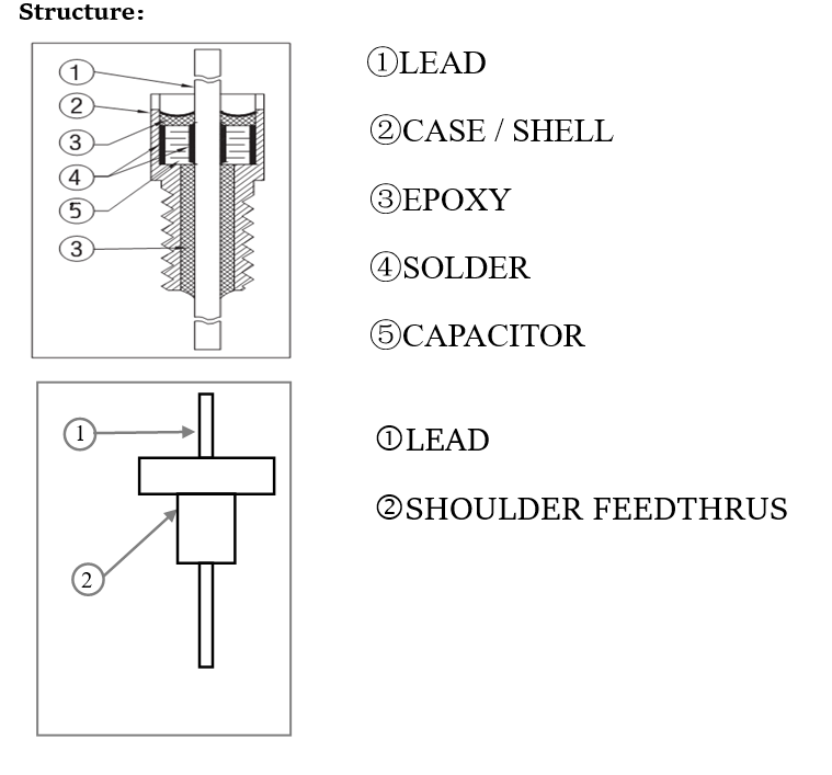
Bushing Mount EMI Feed-thru Filter
Install revolving force
Using the relative case recommend install revolving force when you install filter to the separator or panel.This is an important point.otherwise,the inside capacitor will be damage by the case distortion.The maximum install torsion should be adopt the recommend thread 50% when you install to screw hole.Just the Torque control at:0.2Nm(M3),0.3Nm(M4), 0.9Nm(M6).
Install tool
Hexagon filter should need the proper tube to fix.Circular filter need following method(don’t use pincers,it will damage the filter)slotted top circular filter process screw hole with the special tool.
Ground
In order to make sure filter working,filter case must be connect to panel ground enough,that it can supply the effective path for interference.Never use binder lock-on,if you have to use you can do it after the finish of installation.
Minimum thickness of panel
Customer need to attention sometimes EMI filter has the relief groove between thread and case.It will appear some problems about thread and hole close fit and fixed-position of filter when the insert thickness is smaller than relief groove. So the panel thickness should be larger than relief groove if it is possible.
Maximum thickness of panel
Make sure the nut perfect as the situation of using washer.
Solder Mount C/Pi Filter
- Pay attention to control the filter’s inside ceramic capacitor will not damage when it appear abrupt thermal shock.
- Control the speed as 2℃ /sec when you preheat up. In fact,it up to the different panel can component,these are good success examples during the 1.5-4℃ /sec.
- Adopt soaking area is necessary before soldering,it made the panel temperature equally and well.any panel of return-deform will appear the damaged stress.
- Soldering materials is SN60,SN62(Non-ROHS),Sn-0.7Cu,Sn-Ag(ROHS) and equal with that.
- Soldering time should be reduce the minimum,and the soldering temperature control more than 380℃(fit for the solder-in type).Cooling down the room temperature use the natural cooling.Let the temperature stress of soldering reduce common,avoid flow cooling.it will appear temperature damage if you use the force flow cooling.Use the cooled liquid to wash will broke the ceramic capacitor after soldering.
Terminal soldering:
Whatever screw type or solder type,should be attention when you soldering guide pin as follows:
- The temperature of soldering iron side didn’t over 380℃,soldering time not longer than 3-5 seconds,and reduce the danger of abrupt shark broke capacitor.
- Soldering materials is Sn60,Sn62(Non-ROHS),Sn-0.7Cu,Sn-Ag(ROHS) and equal with that.
- Use the radiator between soldering point and capacitor body,specially the soldering time is long.
Guide pin pending and trim:
Filter guide pin’s bending not do during 4mm of epoxy seal,trim guide pin need to brace firstly.